Factory Specs & Quotes
Get unbranded (white-label) PDF datasheets and custom MOQ options directly from our engineering team. Fast 24-hour response. 100% Privacy Guaranteed. No spam.

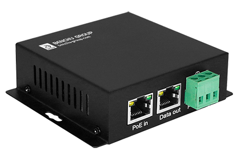
A 60W PoE++ splitter converts a standard 44–57V IEEE 802.3bt PoE input into a regulated 12V DC output of up to 5A. As an IEEE 802.3bt-compliant powered device (PD), it draws power from a PoE++ switch and delivers stable 12V DC to PTZ cameras, wireless access points, industrial controllers, edge computers, and other high-power 12V devices.
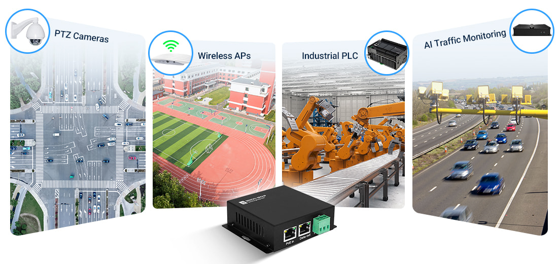
To qualify as the industry-standard choice, an active high power PoE splitter must sustain operational continuity under abrupt, highly fluctuating electrical loads:
1. Pan-Tilt-Zoom (PTZ) High-Speed Security Cameras
High-draw PTZ speed domes run precision mechanical positioning motors, heavy heating elements, and dense IR light arrays simultaneously. During startup routines or high-speed panning cycles, current demands spike significantly. Using a dedicated PoE splitter 12V 5A safeguards these systems against critical voltage sags and rolling reboots.
2. Enterprise Multi-Gigabit Wireless Access Points (APs)
Next-generation Wi-Fi 6E/7 architectures utilize heavy internal RF processing, wide channels, and high-density MIMO arrays. Delivering robust, continuous current through an ultra PoE splitter avoids performance throttling, data packet drops, and device disconnection during periods of peak client density.
3. Heavy-Duty 12V DC Industrial Automation Systems
Compact computing gateways, remote IoT controller modules, and centralized IP-access control hardware demand absolute voltage precision. Utilizing a calibrated regulated 12V DC splitter isolates the localized load from long-distance copper resistance and electrical interference, optimizing hardware service life.
To qualify as a resilient, carrier-class power solution for high-availability edge deployments, a hardware splitter must satisfy strict electrical and physical tolerances:
To ensure optimal transmission balancing and prevent physical equipment damage, field deployment technicians must implement connections using the following step-down workflow:
Connect the primary IEEE 802.3bt Input line sourced from the distribution switch directly to the shielded RJ45 port marked "PoE In".
Route a standard shielded Ethernet patch cord from the "Data Out" RJ45 port to the Gigabit LAN interface of your edge appliance.
Seat the copper power wires firmly into the vibration-resistant green industrial terminal block (or matching DC barrel pin) to energize your terminal load.
Q: What causes severe voltage attenuation in direct low-voltage 12V DC runs over 50 meters?
A: Low-voltage current transmission suffers intensely from loop resistance in copper conductor lines. Attempting to push 12V natively over a long distance triggers a massive voltage drop, resulting in hardware instability or shutdown under high operational states. Transitioning power transmission to standard, high-voltage PoE and stepping down locally with an isolated 60W PoE++ splitter preserves power integrity, maintaining stable, regulated 12V delivery across standard 100-meter limits.
Q: Why is a 3.5KV galvanic isolation barrier essential in outdoor PTZ and AP deployments?
A: Outdoor physical units are highly vulnerable to induction surges, nearby lightning strikes, and ground loop potentials. Integrating an isolated PoE++ splitter with a 3500V galvanic barrier physically decouples input and output circuits. This critical defense wall absorbs high-voltage surges locally, preventing terminal equipment failure and shielding upstream core network switches from back-feeding overvoltage destruction.
Don't let unstable edge power delivery budgets and fragile consumer-grade accessories compromise your deployment profit margins. Speak directly with a BENCHU GROUP system design specialist to receive a comprehensive wiring evaluation, custom voltage profiling, or an enterprise project volume quote.
REQUEST A TECHNICAL CONSULTATION & BULK QUOTE NOW Envia-nos um email
 Ligue para nós
 Endereço
5F, Block5, GuangmingGu Industrial Park, Matian Villiage, Guangming Disitrict, Shenzhen, China



 Rede IPv6 suportada
 Português